Al's Robotics.... The Robux Project
| Site
Index |
| Robotics Events |
| Latest
News |
New site layout implemented, what do you think? |
new information added to the Robux Project Pages click here for more info |
My Robux
The sketches below will give you a rough idea as to what I have in mind for my chassis for the Robux Project. Every time I think about it or look around web sites (especially Ebay) I end up adding more and more complicated bits to the chassis, Tut Tut.
Quick Specs:
- 70 Watt 12 Volt worm gearbox wiper motors
- 4 independent pneumatic suspension system
- Aluminium and steel construction
- Custom machined wheels
- 12 Volt sealed lead acid batteries @ 6 Amps
Chassis
The chassis will be a hybrid construction of Aluminium and Steel to keep both weight and strength balanced (I hope).
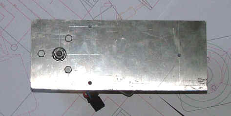
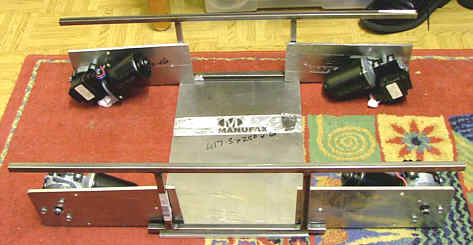
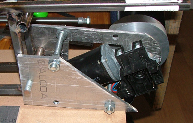
Photos below are of the 6 mm thick 5083 grade aluminium motors mounts, this aluminium is pretty tough stuff (not like any of that rubbish you buy in DIY shops)
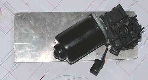
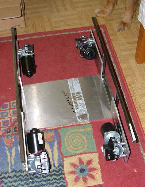
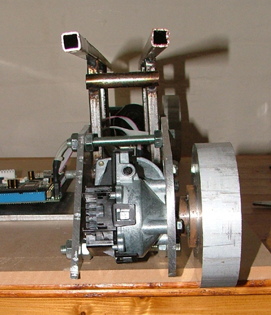
Photos below are of the steel chassis and aluminium base pan + the motors
Pneumatics / Suspension
Pneumatically controlled suspension, ok this idea started out just as adding a little suspension using springs to allow the robot to drive over slightly uneven terrain, ha now it’s got a little more involved! I came across some pneumatic cylinders on Ebay and they were cheap with a capital C so I had to buy them. Thus I’m now building a robot with actively controlled suspension. I guess most people will not bother doing anything like this so any software I write for the Robux Project and active suspension will either use separate hardware / firmware or come as a module that can either be included in the x86 software install or not.
Motors
The motors are from technobots and again were another bargain. 10 motors for 20 quid, now you cant go wrong with that one. These motors produce about 70 Watts at 12 Volts DC and plenty of torque. All of these motors are right handed (mm that depends on how you hold it) hence they at slightly funny angles in the sketches. It may also be required that the speed controllers for these motors be adjusted, as most motors will run faster in one direction then the other, will have to wait and see about though.
Update: 05/11/05
The Motor mounts are now finally completed and ready to be bolted onto the chassis. Just need to find a supplier of M14 studding now, mmm that’s not so common.
Back view
Front view
Side view
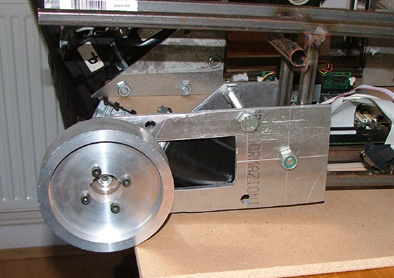
The chassis is starting to take place nicely now, you should be able to see from the photos below how it will finally look when I have completed it. I’m going to use 4 lengths of M14 threaded rod to link the two sides of the robot together, this should make it easy to repair and expand it latter on


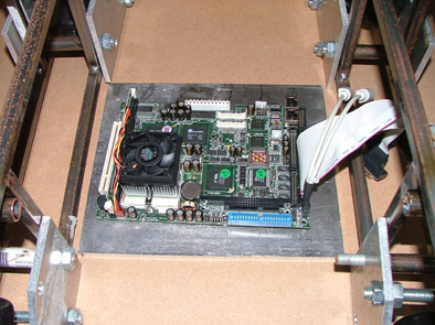
Chassis photo with the Robo-603 motherboard
Back to the Robux Project index
Web pages built and © by A R Martin E-mail at:
Home-page Robots Tutorials Links E-mail Circuits Events BEAM PIC-Microchip Robotics-Shop Computers FMM-RobotWars Sponsors Suggested-reading Ebay-Listings Serial-Speed-Controllers MicroMouse Walkers Driller-Killer Laptops Excaliber-Robot Retox-Drill-Robot Robot-motors Robot Builder Google Robux Project gorobotics Robot Cafe Robotics Solar Navigator PIC Axe Tech Supplies MUTR GSM Control Home Automation Baja Beetle VW Baja Qtronics Design - Electronics & Firmware Design