Al's Robotics....
| Site
Index |
| Site Index |
| Rambo Auto Tools |
| Robotics Events |
| Linux Computing |
| Reading Books |
| Latest
News |
new information added to the Robux Project Pages click here for more info |
LOGIC
I've set this page to hopefully help people to get into the building blocks of logic that can be used in robotics, it's probably of more interest to those of you that are interested in BEAM robots as BEAM is based around simple logic functions. If you have questions or ideas that you want to share please join my robotics club there you will be able to talk to me and others about it, this is the link for it:
http://uk.groups.yahoo.com/group/alsrobotics
Designing
a sequential logic circuit:
To do this you first need to set your self a goal of what you want the
circuit to do it may be preferable to produce a flow chart to help you
plan out the steps the circuit needs to take in order to get it to do
what you want. Once you know what it should do you will need to produce
a logic table, for instants a logic table for an inverter or NOT gate
would be this:
A = input and Q = ouput
| A |
Q |
| 0 |
1 |
| 1 |
0 |
So as you can see all the steps that the gate takes are logical that's why that name was given to them. A non inverting gate would be the opposite to that truth table so if you put logic 1 in you would get logic 1 out again. Such gates are usually used for buffering or strengthening the signal input.
So now to look at something a little bigger:
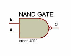
A NAND gate which is basically a AND get with a NOT gate stuck to it's output to produce the NOT AND gate (NAND). This gate has 2 inputs and 1 output, the truth table for this gate looks like this:
A = input, B = input and Q = ouput
| A |
B |
Q |
| 0 |
0 |
1 |
| 0 |
1 |
1 |
| 1 |
0 |
1 |
| 1 |
1 |
0 |
Obviously this gate has more usage's then the one above for instants it could be used for driving a motor with 2 sensors attached to it, so when both sensors are at logic 0 the motor turns on, if one of the sensors state changes to logic 1 the motor still turns but if both sensors states change to logic 1 then the motor will stop. Note that in this setup there would need to be an output stage to the logic circuit in order to drive the motor as logic gates are only capable of supplying a few mA.
It is important to consider the needs of logic gates as they require no more then 5 Volts on there gates anymore then this could and most probably will blow the gates, needless to say it wont be working again. It's this 5 volts that is know as TLL referring to logic at 5 Volts, logic is also talked about as 1 or 0, 1 being +5 Volts and 0 being 0 Volts.
JK flip-flop:
The JK flip-flop is formed by using two gates, these are NOR gates although it possible to use other gates and even transistors. It's virtually 1 bit of RAM and is the basis for modern computer RAM, remembering that 7 bits make a byte (noting that it starts from 0 so there is 8 JK flip-flops to the byte) so just think how many of these are in your PC, it's a good thing they can be made so small.
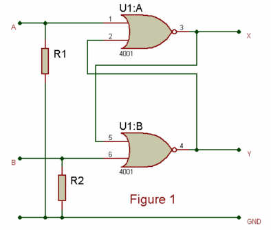
The diagram for the construction of a JK flip-flop looks like this (figure 1):
R1 and R2 are placed in the circuit to avoid the state of the JK from changing due to the volatility of the gates being susceptible to spikes etc. The logic table for the JK looks like this:
Here again A = input, B = input and X = output, Y = output
| A |
B |
X |
Y |
| 0 |
0 |
Stay the same |
Stay the same |
| 0 |
1 |
0 |
1 |
| 1 |
0 |
1 |
0 |
| 1 |
1 |
toggle |
toggle |
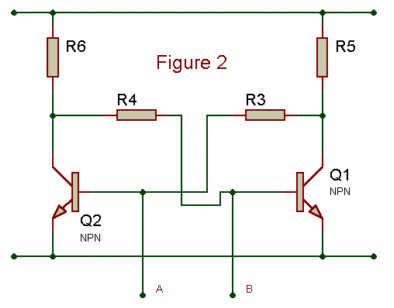
A slightly more primitive version of a JK flip flop using transistors would look something like this (figure 2):
Web pages built and © by A R Martin E-mail at:
Home-page Robots Tutorials Links E-mail Circuits Events BEAM PIC Microchip Robotics Shop Computers FMM-RobotWars Sponsors Suggested reading Ebay Listings Serial Speed Controllers MicroMouse Walkers Driller-Killer Laptops Excaliber Robot Retox Drill Robot Robot motors Robot Builder Google Robux Project gorobotics Robot Cafe Robotics Solar Navigator PIC Axe Tech Supplies MUTR GSM Control Home Automation RC tracker Qtronics Design - Electronics & Firmware Design Artist R C Martin http://www.speedace.info/qtronics.htm http://www.solarnavigator.net/qtronics.htm http://www.elecdir.com/site/store/23197/index.html http://www.robotbuilder.co.uk/forum/topic.asp?whichpage=2&TOPIC_ID=861ᶱ